Ion Battery Charger Circuit with Automatic Cut Circuit Diagram To conclude, this simple li-ion battery charger circuit is important to recognize the limitations of a basic LM317 circuit, even though it can produce a working charger. Use specialized Li-ion charger ICs with built in safety features for dependable and safe charging, particularly for expensive batteries or high power applications. References Building the 3.7V Li-Ion battery charger. Construction of this charger circuit is undoubtedly a difficult exercise for many beginners and hobbysists because the task calls for perfect skill in SMD soldering/prototyping. Fortunately, readymade Li-Ion Battery Charger Modules are now available at many online stores.
You cannot "trickle charge" a lithium battery. If you keep pushing current in, the voltage just keeps on rising until the battery catches fire. If you keep a constant voltage, the current
How To Make A Homemade Battery Charger: A Step Circuit Diagram
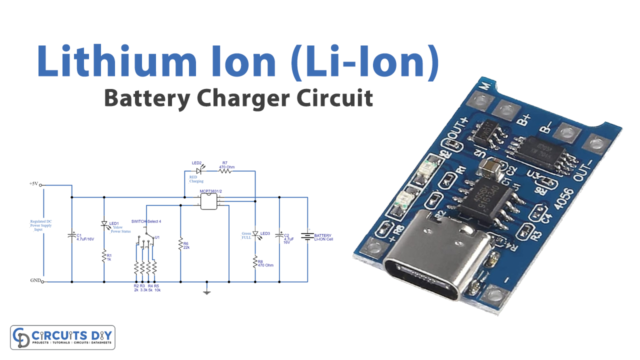
The circuit diagram for 18650 Lithium Battery Charger & Booster Module is given above. This circuit has two main parts, one is the battery charging circuit, and the second is DC to DC boost converter part. The Booster part is used to boost the battery voltage from 3.7v to 4.5v-6v. All these things are assembled on TP4056 Li-ion battery charger breakout board whose link is mentioned in step No-2. We need to do only two things, give a voltage in the range of 4.0 to 8.0 V at input terminals and connect a battery at B+ and B- terminals of TP4056. Place 7805 voltage regulator circuit; use glue gun to make a firm joint

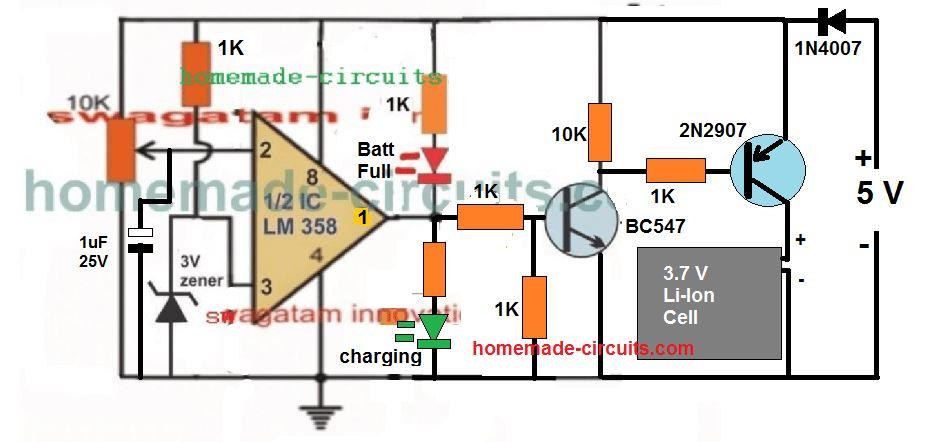
Most of the rechargeable battery has common problem of over charging and over discharging. we need a smart charging solution that protects our battery from over charging and damage cause by over charging. This lithium battery charger circuit automatically cut off the charging process when the full charge limit of battery is reached (i.e-4.2V) . The following Li-Ion battery charger circuit very efficiently follows the above conditions such that the connected battery is never allowed to exceed its over charge limit. When the IC 555 is used as a comparator, its pin#2 and pin#6 become effective sensing inputs for detecting the lower and the upper voltage threshold limits depending upon The suggested 220V Li-ion Battery Module charger circuit is depicted in the accompanying figure. Let's examine how it operates in more depth using the following description: Circuit Diagram In order for the SCR to always start with a momentary switch on anytime the circuit is switched on, irrespective of whether or not the battery is attached
